

Utilize the anchoring-to-concrete provisions to resist shear using post-installed rebar
The term “shear friction” used in reinforced concrete design refers to some form of shear transfer across a plane. The American Concrete Institute (ACI) standard titled Building Code Requirements for Structural Concrete (ACI 318) includes specific provisions for reinforced concrete design when considering shear friction. ACI 318-19 Section 22.9 is titled Shear friction. The Section 22.9 design premise for an interface between two different concretes is that reinforcing bars developed (i.e., designed to yield) on each side of the interface will clamp the two concretes together, thereby permitting shear transfer across the interface. The bar development length is calculated per the tension development provisions in ACI 318-19 Chapter 25. Tension development length calculations are predicated on bars installed close to a fixed concrete edge where splitting failure could occur. The bars must be embedded deep enough to preclude splitting failure, thereby permitting yielding to occur. However, when bars are installed at a large distance from a fixed concrete edge, pullout failure or concrete breakout failure are more likely to occur in lieu of splitting failure. Therefore, development length calculations for bars installed at a large distance from a fixed concrete edge should be predicated on embedding the bars deep enough to preclude pullout and concrete breakout failure. The embedment depth calculated to yield bars installed at a large distance from a fixed concrete edge could be less than the development length calculated per Chapter 25 provisions, or it could be greater due to the influence of bar spacing.
This paper will discuss shear friction applications (Section 22.9) for which post-installed reinforcing bars are designed to yield using ACI 318-19 anchoring-to-concrete tension provisions instead of designing the bars for tension development per Chapter 25 provisions. This design premise is feasible when bars are installed at edge distances large enough to preclude splitting failure. In keeping with the design premise, post-installed reinforcing bars developed (i.e., designed to yield) on each side of a shear interface using anchoring-to-concrete provisions will clamp the two concretes together, thereby permitting shear transfer across the interface.
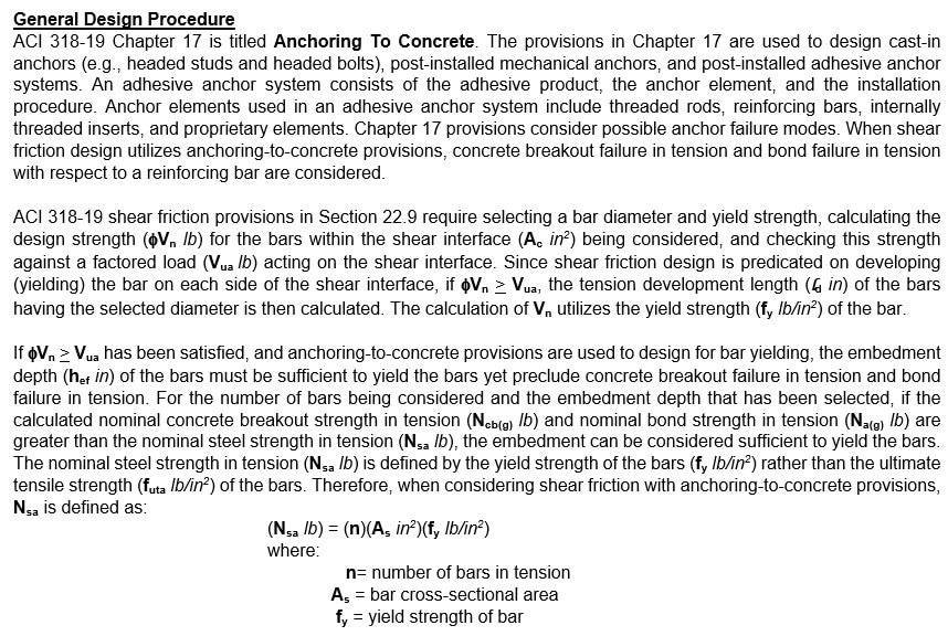
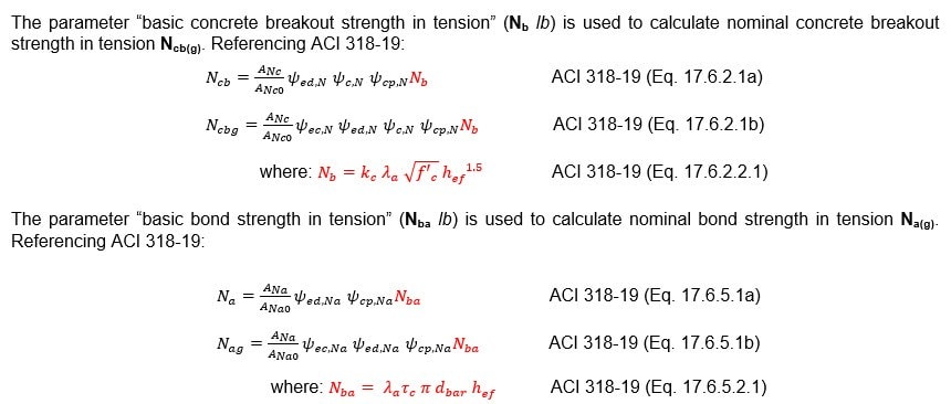
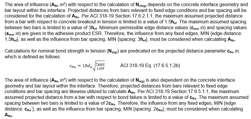
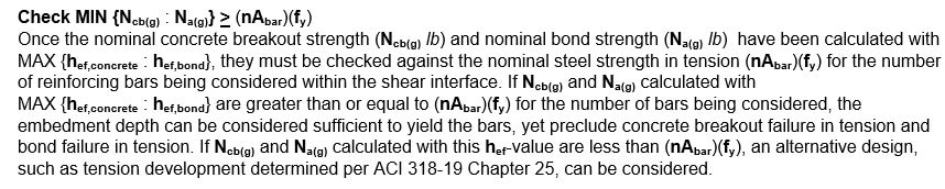
Consider a group of post-installed bars being designed for development in tension. Let the nominal steel strength be defined as (nAs)(fy), where “n” corresponds to the number of bars. If the nominal concrete breakout strength calculated for the bars (Ncb(g)) and the nominal bond strength calculated for the bars (Na(g)) are both greater than (nAs)(fy), the yield strength of the bars controls the design. By equating (Nsa lb) for a single bar, i.e., Nsa = (As)(fy), to (a) Nb calculated per Eq.(17.6.2.2.1) and (b) Nba calculated per Eq. (17.6.5.2.1), and solving for hef; an embedment depth corresponding to yielding the bar can be determined. The greater of the hef-values that have been calculated can then be used to calculate (Ncb(g) lb) and (Na(g) lb) for the number of bars (n) being developed in tension. If Ncb(g) and Na(g) calculated with this hef-value are both greater than (nAs)(fy), the embedment (hef) can be considered sufficient to yield the bars yet preclude either concrete breakout failure or bond failure. If either Ncb(g) or Na(g) calculated with the hef-value are less than (nAs)(fy), the embedment (hef) is not sufficient to preclude concrete breakout failure and bond failure. A different embedment and/or a new bar diameter and/or steel grade must be selected, and the design procedure repeated. The next section will explain the design procedure in detail.
Post-Installed Reinforcing Bars Designed to Yield Using Anchoring-to-Concrete Provisions
Post-installed reinforcing bars can be designed per ACI 318-19 provisions if the adhesive product used to install the bars has been evaluated per a recognized testing program. Hilti adhesive anchor systems are evaluated per the International Code Council Evaluation Service (ICC-ES) acceptance criteria, Acceptance Criteria for Post-Installed Adhesive Anchors in Concrete Elements (AC308). This is to (a) demonstrate compliance “in the opinion of ICC-ES” with the International Building Code (IBC), and (b) obtain data for designing the adhesive anchor system using ACI 318 provisions. Adhesive products that satisfy the provisions of the test program outlined in AC308 Table 3.2 can be used to post-install reinforcing bars designed per ACI 318 anchoring-to-concrete provisions. Adhesive products that satisfy the provisions of the test program outlined in AC308 Table 3.8 can be used to post-install reinforcing bars designed per ACI 318 development and splice provisions.
Per Table 3.2 criteria, the embedment depth (hef in) for a post-installed reinforcing bar designed with ACI 318 anchoring-to-concrete provisions (e.g. ACI 318-19 Chapter 17 provisions) is limited to a maximum depth of 20 bar diameters: hef less than or equal to 20(dbar in). Per Table 3.8 criteria, the maximum embedment depth for a post-installed reinforcing bar designed with ACI 318 development provisions (e.g. ACI 318-19 Chapter 25) is 60 bar diameters: hef less than or equal to 60dbar. Since Hilti adhesive products that satisfy the test program in AC308 Table 3.2 can be designed with anchoring-to-concrete provisions, and products that satisfy the test program in AC308 Table 3.8 can be designed for development (i.e. yielding); Hilti adhesive products that satisfy the test programs in AC308 Table 3.2 and Table 3.8 can be assumed to be acceptable (with possible modifications) for development (yield) design using anchoring-to-concrete provisions at embedment depths up to 60dbar. Embedment depths that range between 20dbar and 60dbar (20dbar less than or equal to hef less than or equal to 60dbar) are within the range of tension development lengths (ld in) calculated per ACI 318-19 Chapter 25.
ACI 318 provisions for calculating ld are concerned with embedding a bar deep enough to “develop” the yield strength without splitting failure occurring. “Splitting failure” refers to cracking and splitting in the concrete around bars in tension.
Designing post-installed reinforcing bars for yield using anchoring-to-concrete provisions considers the possibility of concrete breakout failure or bond failure in lieu of splitting failure by considering embedment depth, spacing between bars, any fixed edge conditions, and product-specific parameters such as the characteristic bond stress of the adhesive (tk,c lb/in2).
Reference the illustrations below. A post-installed reinforcing bar is designed for development on each side of a shear interface. In the context of this paper, the post-installed end can be designed for development using Chapter 17 anchoring-to-concrete provisions. Since the post-installed end of the bar is installed into existing (i.e., hardened) concrete, it must be straight. However, the bar end around which the new concrete will be placed can be straight or hooked. If the new concrete has sufficient depth, the part of the bar in the new concrete can be designed with a straight development length (ld in). Otherwise, if the new concrete depth is limited to preclude design for (ld ), the part of the bar in the new concrete can be designed with a hooked bar development length (ldh in). In the context of this paper, when a post-installed reinforcing bar is being designed for development on each side of a shear interface, the part of the bar in the existing concrete could be designed using Chapter 17 anchoring-to-concrete provisions. However, the part of the bar in the new concrete must be designed using Chapter 25 development provisions.

Design data for adhesive anchor systems evaluated per the test programs in AC308 is given in an ICC-ES evaluation report (ESR). This data is product-specific and can be used to design the adhesive system with ACI 318 provisions. With respect to post-installed reinforcing bars, data for minimum geometry requirements, bar spacing, edge distance and concrete thickness derived from the test program outlined in AC308 Table 3.2 will be given in tables within the ESR. This data is relevant when designing bars with ACI 318 anchoring-to-concrete provisions. The ESR will also give data for bar spacing and concrete cover derived from the test program outlined in AC308 Table 3.8. This data is relevant to designing bars with ACI 318 development provisions. These parameters differ from the parameters for anchoring-to-concrete provisions. Therefore, when designing post-installed reinforcing bar for development using anchoring-to-concrete provisions, always follow the geometry parameters for anchoring-to-concrete provisions given in the design tables.




Summary
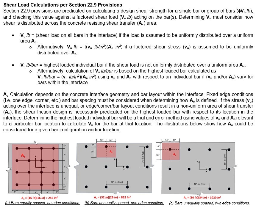
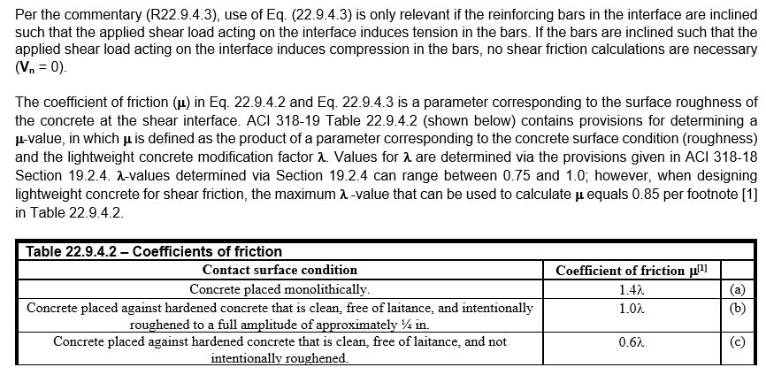
This paper discussed how shear friction design (e.g., ACI 318-19 Section 22.9) could be performed with post-installed reinforcing bars designed for yield using ACI 318-19 anchoring-to-concrete tension provisions instead of ACI 318-19 Chapter 25 tension development provisions. This design premise is feasible when concrete breakout failure and bond failure preclude splitting failure. In keeping with the design premise for shear friction in Section 22.9, post-installed reinforcing bars that can be developed (i.e. designed to yield) on each side of a shear interface using anchoring-to-concrete provisions are assumed to clamp the two concretes together, thereby permitting shear transfer across the interface.
Additional Resources
Design Guides
Hilti Post-installed Reinforcing Bar Design Guide
Hilti Post-installed Reinforcing in Fire Conditions Design Guide
Design Software
PROFIS Engineering
Hilti Post-Installed Rebar White Papers
* Post-installed Reinforcing Bar Design Options: An Overview
* Shear Friction Design using the Hilti Method for Post-installed Rebar Design
* Design for Yield using Anchoring-to-Concrete Provisions for Post-installed Reinforcing Bar Design
* Extension Design using ACI 318-19 Provisions for Post-installed Reinforcing Bar
* Structural Joint Design using ACI 318-19 Provisions for Post-installed Reinforcing Bar
* Shear Friction using ACI 318-19 Anchoring-to-Concrete Provisions for Post-installed Reinforcing Bar Design
* Shear Friction using ACI 318-19 Provisions for Post-installed Reinforcing Bar Design
* Designing Rebar in Fire-rated Concrete-to-concrete Connections: Frequently Asked Questions
* Designing Post-installed Rebar for Fire Conditions using PROFIS Engineering Whitepaper